
Panorama’s and associated visualisations have been used for a long time in Landscape and Visual Impact Assessment (LVIA) for a landscape. This post is going to explain how to create 53.5˚ panoramic images in TrueViewVisuals. Further posts later will explain the process of creating the other sized visualisations.
Our approach is loosely based on SNH guidelines, however, it could be applied to Highland Council Guidelines or Landscape Institute’s GLVIA.
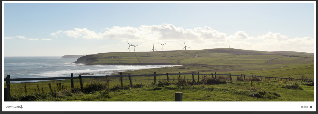
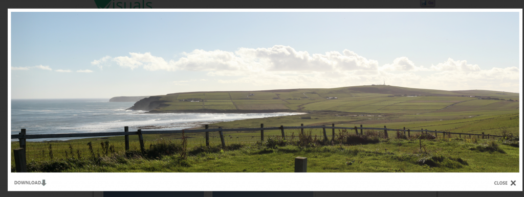
Terminology
We’re going to use the following terminology:
- A viewpoint is a location where a project is going to be assessed from. Its location is required before the process can be undertaken (the base photography should be taken from this viewpoint).
- Base Photography should be taken on a digital camera with a 50mm lens and a full-frame sensor. If this hardware is not accessible, it can be taken on a decent quality digital camera, and the system will cope, but they will not match the standards. You need at least three base photographs to create the 53.5˚ panoramas.
- Renders are taken by adding the project model to the base images. Renders are created in the TrueViewVisuals iPad App.
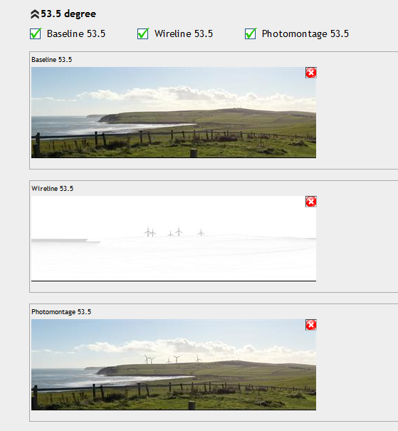
- An Output Image is a wide image composed of several base photographs or renders. There are 3 types of output image:
- Baseline – showing the existing landscape before the project is built. This is made from Base Images.
- Wireline – A wireline representation of the landscape.
- Photomontage – showing what the effect of the project will be on the landscape. This is made from the renders.
- An output image group is a collection of output images taken from a viewpoint and all representing the same view.
Process
To illustrate this process, we are going to use an example project we have worked on Orkney. This process breaks down into 4 sections: setup, then create baseline, wireline and photomontage images.
Setup
- Upload 3 photos to viewpoint in the portal
- Sync the gallery on the iPad (downloads from portal to iPad)
- Calibrate each photo to ensure that the wireline matches the terrain (field of view, heading, roll and inclination). Once this is complete, save calibration to ensure we have it available next time.
- Sync to ensure all changes are backed up.
Baseline 53.5
A flow diagram of the process of creating a baseline 53.5 panorama is shown below. From the project page in the portal, we will choose 3 images and then create the 53.5 panorama.
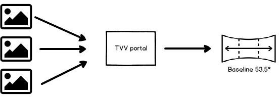
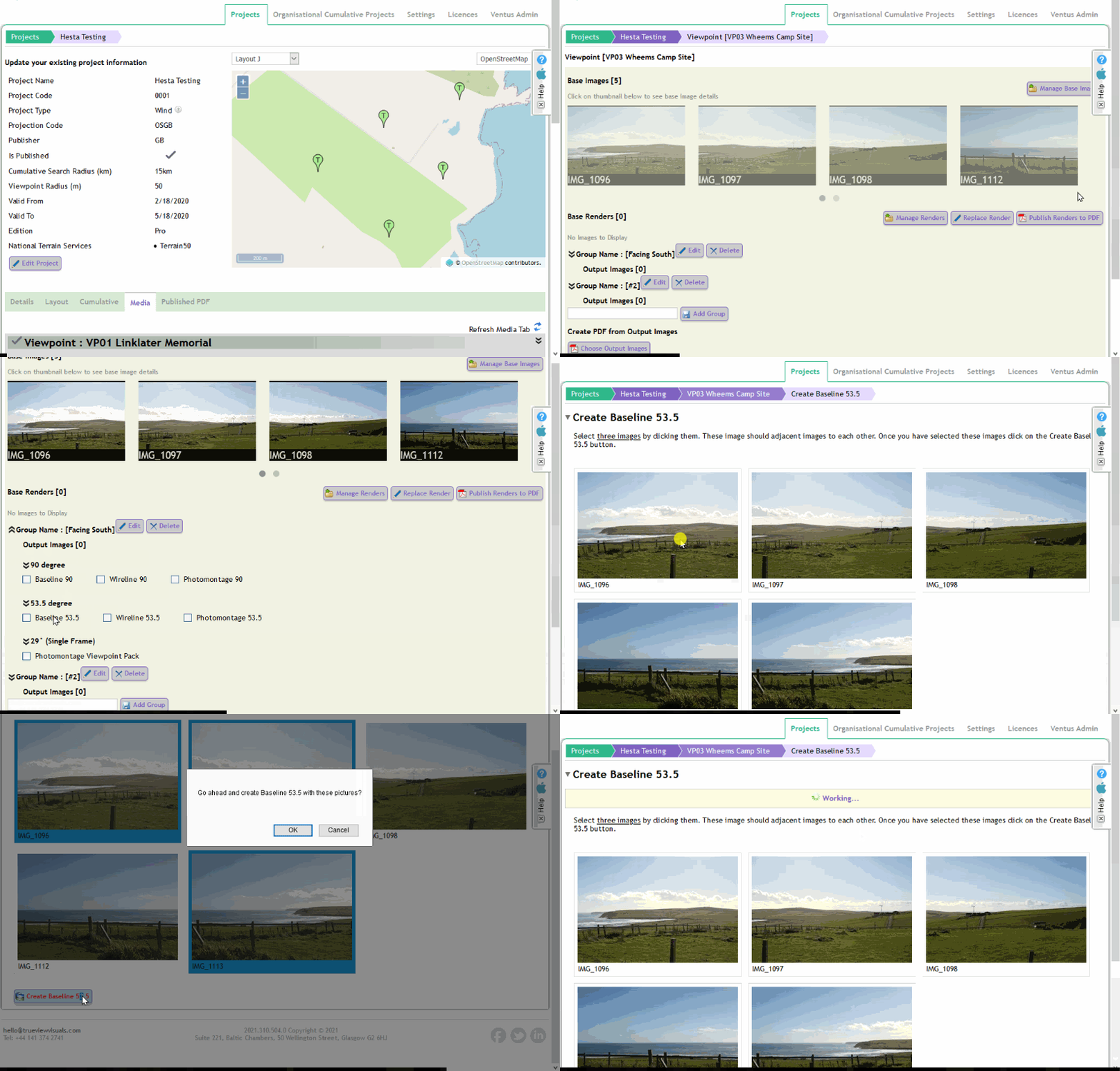
- In the portal go to the media tab or the viewpoint media page, find the output heading group to added the panorama to. Expand the 53.5 degree section. Click on Create baseline 53.5.
- Choose 3 photos and then Create
- Wait – it takes a couple of minutes to complete. This will start the process running and when it is finished the image will be stored in the output image group. You can leave this page while the process is running. The banner across the top will update once the process has completed and you will be able to preview the panorama.
Wireline 53.5
The wireline 53.5 is created in several steps. It starts with the centre base image used in the baseline panorama and photomontage. From that frame on the iPad, the 3 individual parts a wireline 90 are created as renders. Then in the portal, these 3 renders are used to create the Wireline 53.5. The process is drawn out below.
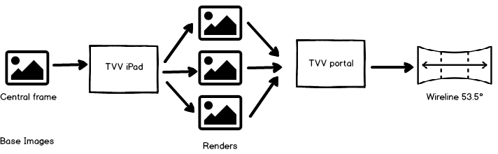
- On the iPad, find the centre frame image and open the full-screen gallery view. Set up the wireline as you want it to look. (e.g. Camera off, grey wireline, and maximize turbine visibility).
- Choose the Render tab and Create wireline90 button (at the bottom).
- Sync the viewpoint to get the images to the portal
Once these renders are in the portal they can be used to create the wireline 53.5.
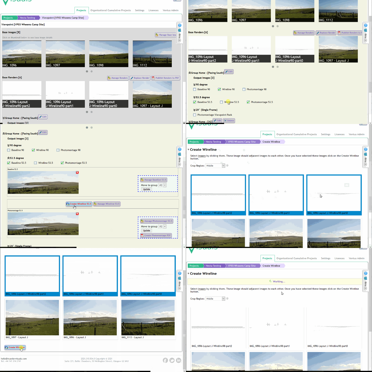
- Find the viewpoint in the media tab expand the group where this is going to be placed
- Choose the Create Wireline 53.5
- Choose the 3 parts of the wireline (they should be called <imageName>-<layout>-Wireline90-part0 / 1 / 2). Click Create Wireline 53.5.
- Wait – it takes less than a minute to complete. This will start the process running and when it is finished the image will be stored in the output image group. You can leave this page while the process is running. The banner across the top will update once the process has completed and you will be able to preview the panorama.
Photomontage 53.5
A flow diagram of the process of creating a photomontage 53.5 panorama is shown below. First, we will use the TVV iPad to create Renders from the base image with the project added. Then from the project page in the portal, we will choose 3 images and then create the 53.5 panorama.
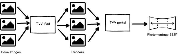
The process to create a Render is as follows:
- On the iPad go to the gallery and open each photo. Ensure calibration is correct and it shows what you need (camera feed, correct layout version, wind speed, lighting and traces).
- Create a render from the current view – from the right-hand panel go to the render tab, check settings and choose next to get to the Create Render button (big button in the middle of the tab). This creates a jpeg of the current view.
- Sync the renders back up to the portal.
Once the Renders are in the portal, they can be used to create the photomontage
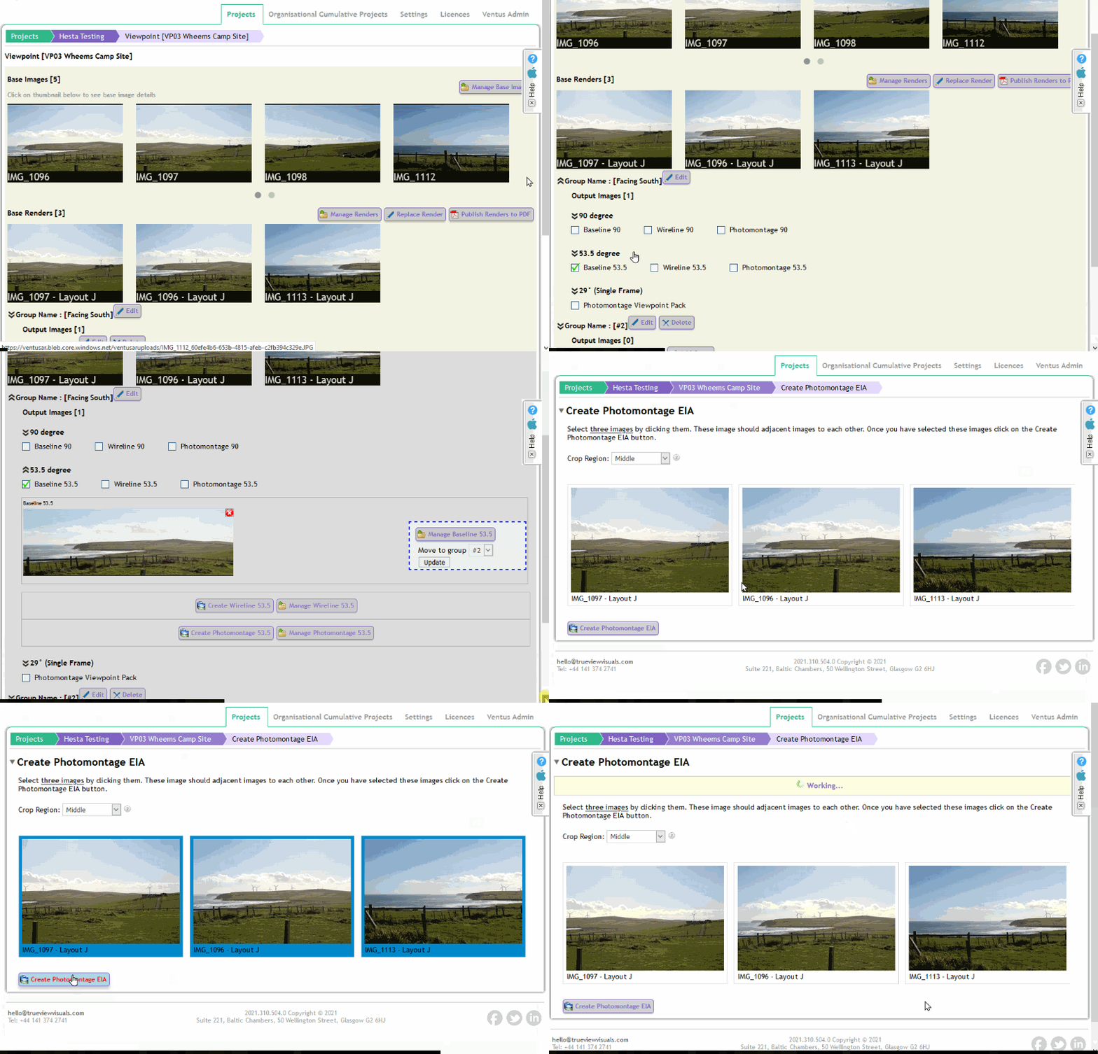
- In the portal go to the media tab or viewpoint media page, find the output heading group to add the panorama to. Expand the 53.5 degree section. Click on Create Photomontage 53.5.
- Choose the 3 renders that will make up this panorama and then click Create
- Wait – it takes a couple of minutes to complete. This will start the process running and when it is finished the image will be stored in the output image group. You can leave this page while the process is running. The banner across the top will update once the process has completed and you will be able to preview the panorama.
Results
Once each of these images have been created, they are stored on the group for the project. They can be used to created PDFs including the metadata for inclusion in reports or for public engagement.
If you have questions about how TrueViewVisuals software could be used to speed up the visualisation process for your project, get in touch at hello@trueviewvisuals.com.