Gallery
Contents
Any captures that have been taken with the TVV app are placed in the Gallery. This is a store of all the captures associated with a single project.
The photo and the associated metadata are stored and the models are superimposed at the time of viewing. This allows flexibility to change the layout of your project without the need to recapture images.
Gallery grid view
The gallery grid view shows a thumbnail of all the captures stored in the gallery. Important information is shown above/below the thumbnail:
- The name or address of the capture. This will be generated at the time of capture based on:
- The viewpoint name (if within 50m of a previously set up Viewpoint)
- The address from a geocode service. This provides address information for a location but is only available if the device is connected to the internet when the capture is taken.
- An empty string if no other information can be identified.
- The location (OSGB or WGS coordinates)
- The Sequence Number
An example of the gallery grid view is shown below:
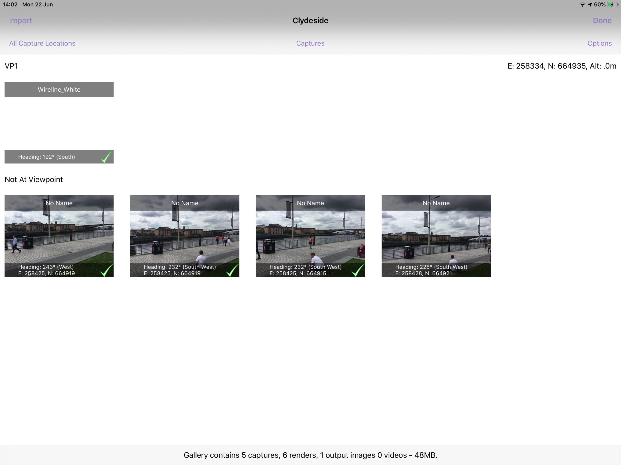
The view can be changed using the dropdown menus to control what is shown in the grid. These are shown across the top of the screen:
- Import– add images from the built-in iOS Photos app to the gallery.
- Location – choices are either not at a viewpoint or one of the setup viewpoints for a project. If the capture is taken at a viewpoint, the capture will be visible under the viewpoint list in the gallery grid.
- Type – captures (can be animated) or renders (static images)
- Options – allows users to manage the items in the gallery grid.
Choosing different options changes what is shown in the grid.
Managing items in the gallery grid
Editing image properties
The name or heading of the capture in the gallery can be edited by long-tapping the capture to enter the edit popover.
To edit either of the properties of the item, select the edit button and enter your desired value into the text area (if an item is not assigned to a viewpoint then the option to create a Viewpoint will also be available). Once the new name has been entered, tapping save closes edit mode.

To create a Viewpoint press Create. If the system has been able to locate an address for this image then the viewpoint name will default to this for the user to edit if required. Tap Save when the new viewpoint name is complete.
Deleting images
Images can be deleted from the gallery by pressing the options button in the top right, which will enable selection. Pressing the Delete button will then remove the selected images from the gallery.

Importing images
Before importing images, you must ensure the TVV app is allowing access to photos on the iPad.
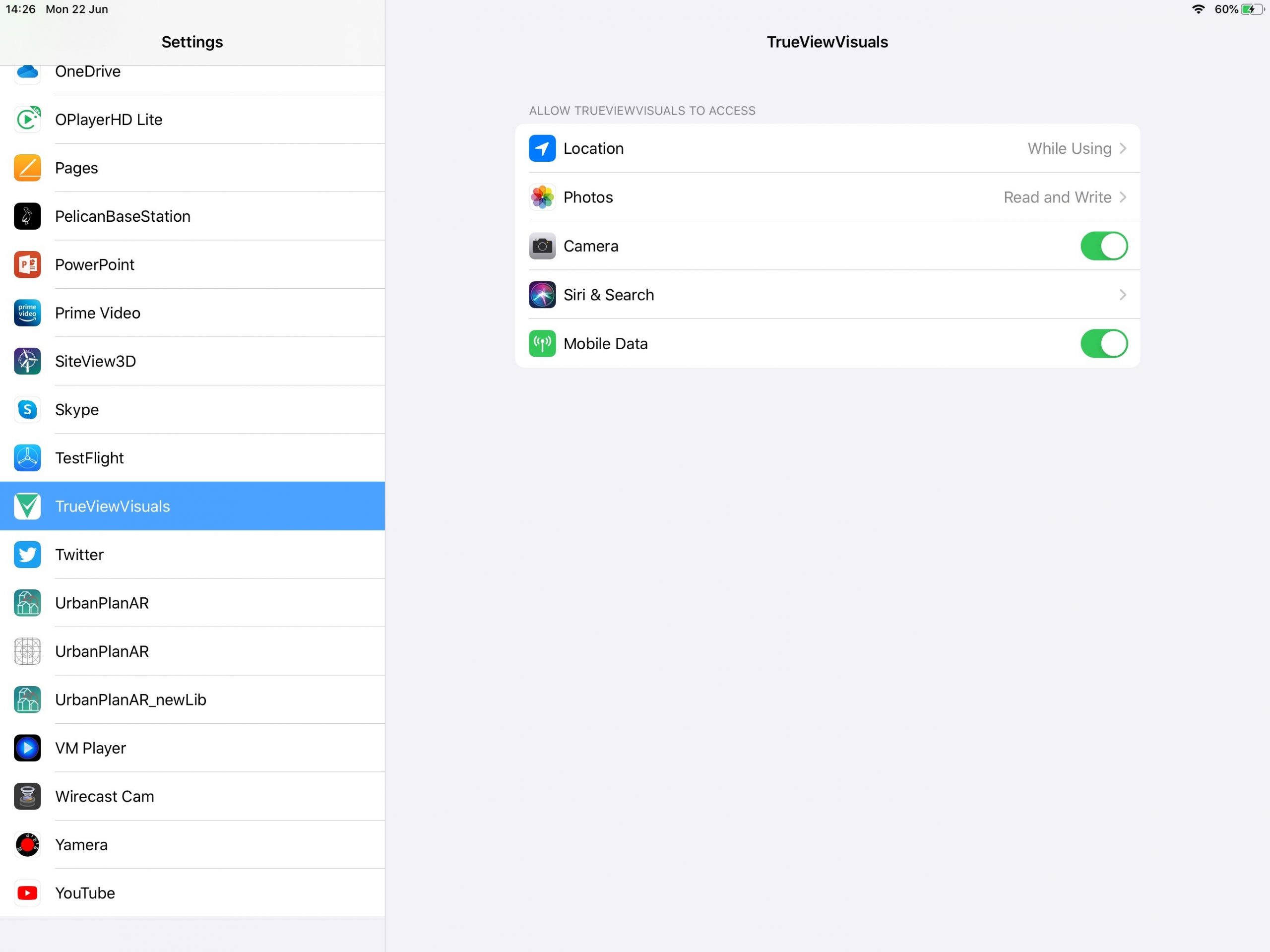
Navigate to the iPad settings, scroll down until you find the TrueViewVisuals settings, ensure Photos is set to Read and Write.
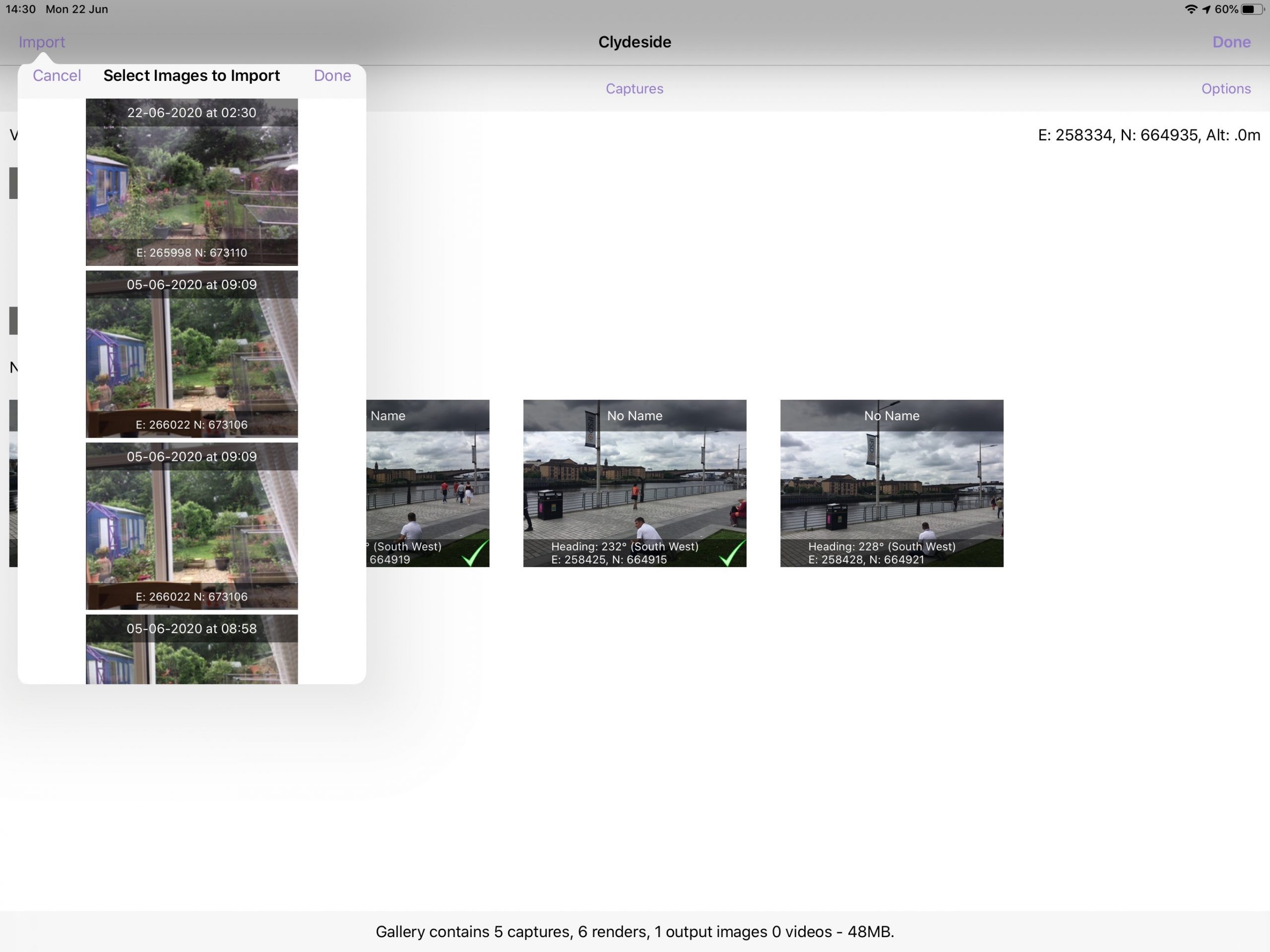
Navigating back to the Gallery within the TVV app – pressing the Import button will present a popover dialogue which gives the option to select multiple images that will be added to the Gallery.
The images that are displayed come directly from the iOS Photos app.
Please note: Only images that have valid a valid GPS location will be displayed.
When the desired images have been selected, they can be imported simply by pressing the done button.
Sync Gallery items with the Portal
All items in the gallery can be easily kept in sync with the portal using the Sync All option in the options menu.
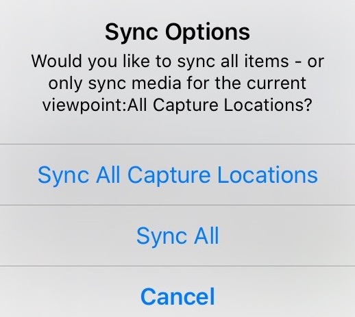
Choosing Sync All will begin the process of backing up all captures and renders from your device up to the portal. There are several steps to this:
- Create a list of captures and renders for this project that needs to be uploaded to the portal
- Copy that list to the portal
- Upload the captures and metadata
- Upload the renders and metadata
- Create a list of captures, renders and outputs in the portal that needs to be downloaded to the device
- Copy that list to the device
- Download the captures and metadata
- Download the renders and metadata
- Download the outputs and metadata
The sync process can take a while to complete. It is dependent on the number of captures you have for an individual project and the speed of your internet connection. We recommend running this process over Wi-Fi.
Conflicts will be handled by choosing the most recent changes. If you are working in a team, the most recent change will overwrite all previous changes.
To sync all data process choose sync all from the options and wait for the dialogue to complete. A step can be skipped by pressing the Skip Step button in the dialogue message.
Viewing a gallery visualisation
To launch a gallery visualisation, tap the thumbnail to open it. This will open the visualisation with the picture in the background and the model super imposed on top. The terrain data will be loaded and will ensure that the models are shown at the correct location on the terrain. If the terrain data has not been downloaded already it will be loaded from the TVV terrain server.
Buttons
The buttons used in the Gallery are described below.
| Button | Location | Action | |
 | Top left | Returns to the previous page | |
 | Top right | Shows internet connection active | |
 | Middle Right | Expands the right-hand panel |
![]() Gallery with right panel
The Gallery contains a right-hand panel that can be accessed using the arrow in the middle right of the screen. The right-hand panel is divided into three tabs:
- View – used to show metadata information about the visualisation as well as create traces and adjust alignment
- Refine – used to control the visualisations
- Render – A wizard used to generate a render

View tab
The metadata is shown in the right panel of the My View visualisation is described below. This metadata shows value and source (and where appropriate accuracy and any calibration that has been used).
The metadata shown is dependant on which domain the project is – wind, solar, building or grid.
| Domain | xxx | Metadata | xxx | Example | xxx | Description |
| All | Easting/Northing | 258425 ±10m (Sensor) | The location the visualisation has been created from. The accuracy is reported by the location sensor, this disappears when relocated as you are placed at a location. The source is shown in brackets and can be “sensor” or “user set” | |||
| All | Heading | 234° (Sensor) | Heading shows the direction the tablet is facing If Grid is shown, this refers to the north reference the device is currently using. Options are Grid, Mag or True depending on whether the convergence and declination transforms are enabled The source is shown in brackets can be “sensor” or “user set” When an offset is added in the calibration panel, the reading will be “185° Grid (sensor + 1.5)”. This states the heading is based on the sensor value + 1.5° of calibration | |||
| All | Inclination | -2° (Sensor) | The inclination of the device. 0° is looking parallel to the ground The source is shown in brackets | |||
| All | Observer Altitude | The altitude of the ground at the location the visualisation is generated from (derived from the terrain model at visualisation location – the altitude from the GPS sensor is ignored). Height overrides are shown after the source e.g. “15.9m (Grid + 1m) | ||||
| All | Cam Alt | 110.1m (Obs + 1.5m) | Camera altitude is always calculated as 1.5m above the observer altitude | |||
| Wind only | Nearest Turbine | 220m | The distance to the nearest turbine | |||
| Buildings only | Nearest Building | 76890m | The distance to the nearest building | |||
| Solar only | Nearest Panel | 71740m | The distance to the nearest solar panel | |||
| Grid only | Nearest Tower | 344650m | The distance to the nearest tower | |||
| All | Angle of view | 60.8° | The horizontal field of view of the current view | |||
| All | Seq. No | {0}N/A | The sequence number is only visible in My View (Camera) mode. |
There are a few common controls that can be controlled from the View tab.
| Domain | xxxx | Control | xxx | Description |
| All | Layout Version | The layout version that is currently being shown. Layout versions are managed in the portal | ||
| All | Start Trace | Allows you to draw a trace around the visualisation | ||
| All | Ref Structures | Show reference structures in My View | ||
| All | Show wireline | Turns the wireline on and off | ||
| All | Wireline opacity | Adjusting the slider changes the transparency of the wireline where 0% is invisible and 100% is fully opaque | ||
| All | Model Opacity | Adjusting the slider changes the transparency of the models where 0% is invisible and 100% is fully opaque | ||
| All | Wireline Colour | Allows the wireline colour to be changed – choices are Red, Green, Blue, Cyan, Magenta, Yellow, Black, White, Grey |
Refine tab
The Refine tab allows control over the way that the visualisation is produced. The controls shown are dependant on which domain the project is – wind, solar, building or grid.
| Domain | xxxxxx | Control | xxx | Description |
| All | Lighting Mode | Changes the lighting to either Realistic or Ambient. | ||
| All | Show Lighting Panel | Opens the lighting panel and allows the date and time to be changed. | ||
| All | 3D Building Data | Turns the 3D building data on and off | ||
| All | Camera Feed | Turns the camera feed off and on | ||
| All | Overlay | Whether to show an overlay showing the terrain model or to exclude it. By default My View is launched with Wirelines enabled, other options include: • Wireline • Base Mapping • No Terrain • Any overlays uploaded through the portal | ||
| Wind only | Turbine Labels | Turns the Turbine Labels off and on | ||
| Wind only | Maximum Visibility | Stops the turbines rotating and faces them to the camera. This provides the most visibility. | ||
| Wind only | Wind Speed | Controls the speed the turbine is animated at: Still, Low, Medium, High, Max, Double | ||
| Wind only | Wind Direction | Controls the direction the turbine blades face | ||
| Wind only | Show Cumulative Panel | Enables or disables all cumulative projects. This is a quick way of turning on / off all the cumulative turbines in one switch. | ||
| Building only | Show as outlines | Changes the building model from solid to showing outlines | ||
| Building only | Colour | Changes the building colour |
Render tab
The Render tab contains a wizard where the user is able to adjust the settings described in the tables above before they create a render. Click Next > or Previous < to navigate through these controls.
| Background | Model | Final Touches |
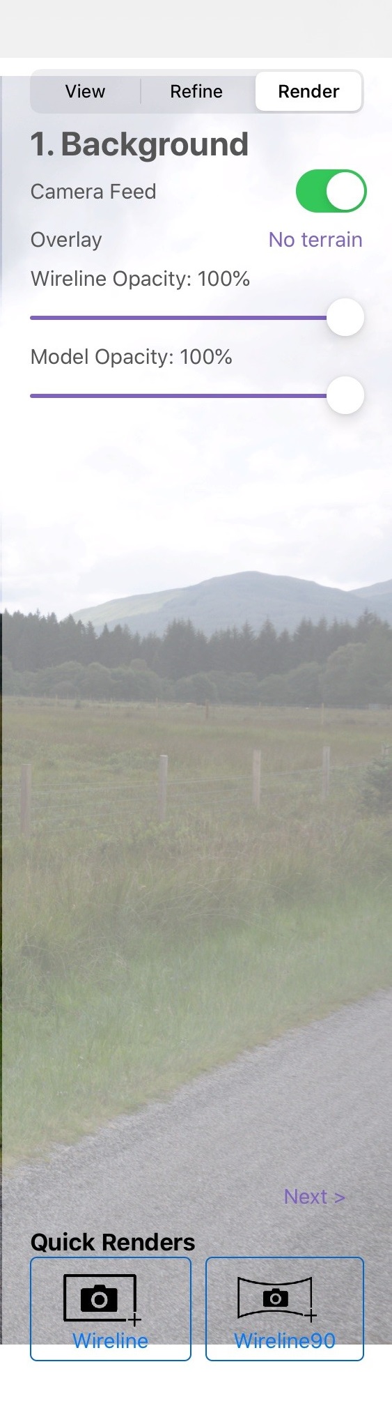 | 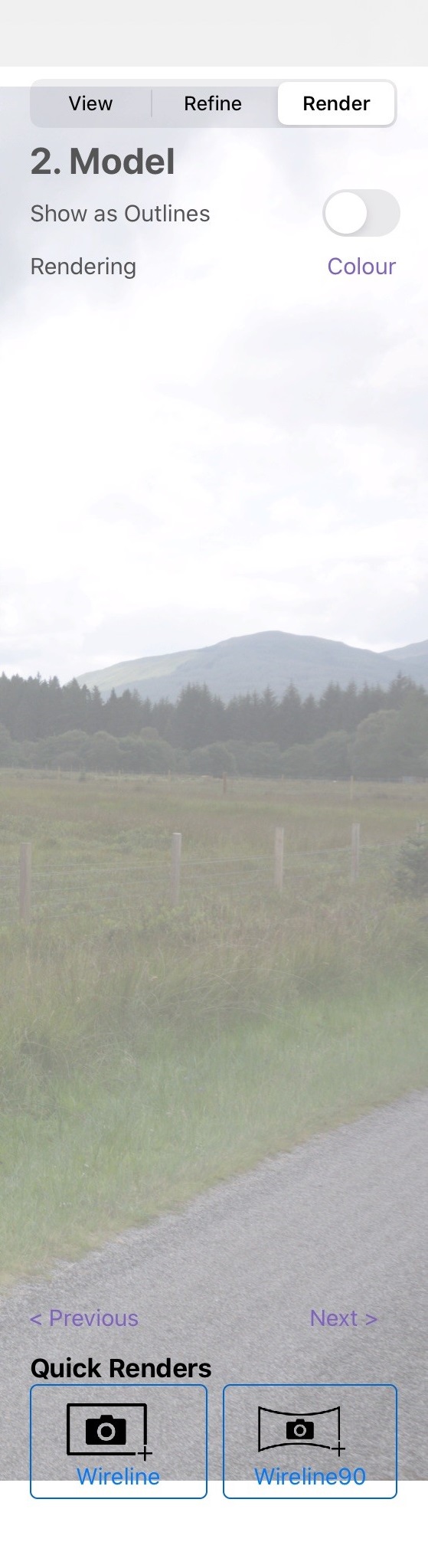 | 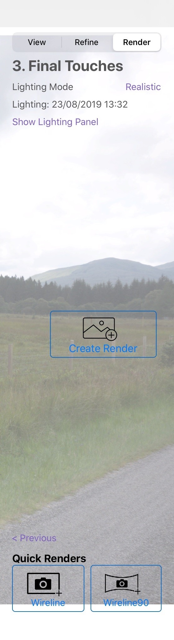 |
The table below describes additional render controls as shown in the images above.
| Control | Description |
| Create Render | Creates a render – this is discussed further in [Viewing Renders] |
| Wireline | Generates a wireline render. See [Creating Renders] |
| Wireline90 | Generates a panorama wireline render. See [Creating Renders] |
Gallery calibration
The calibration panel is shown to the left of the screen and is used to override the values stored when the capture was taken.
The calibration panel is opened using the left-hand expander icon ( middle left). To make the calibration panel obvious, the background is red.
The calibration tools are also found in My View.
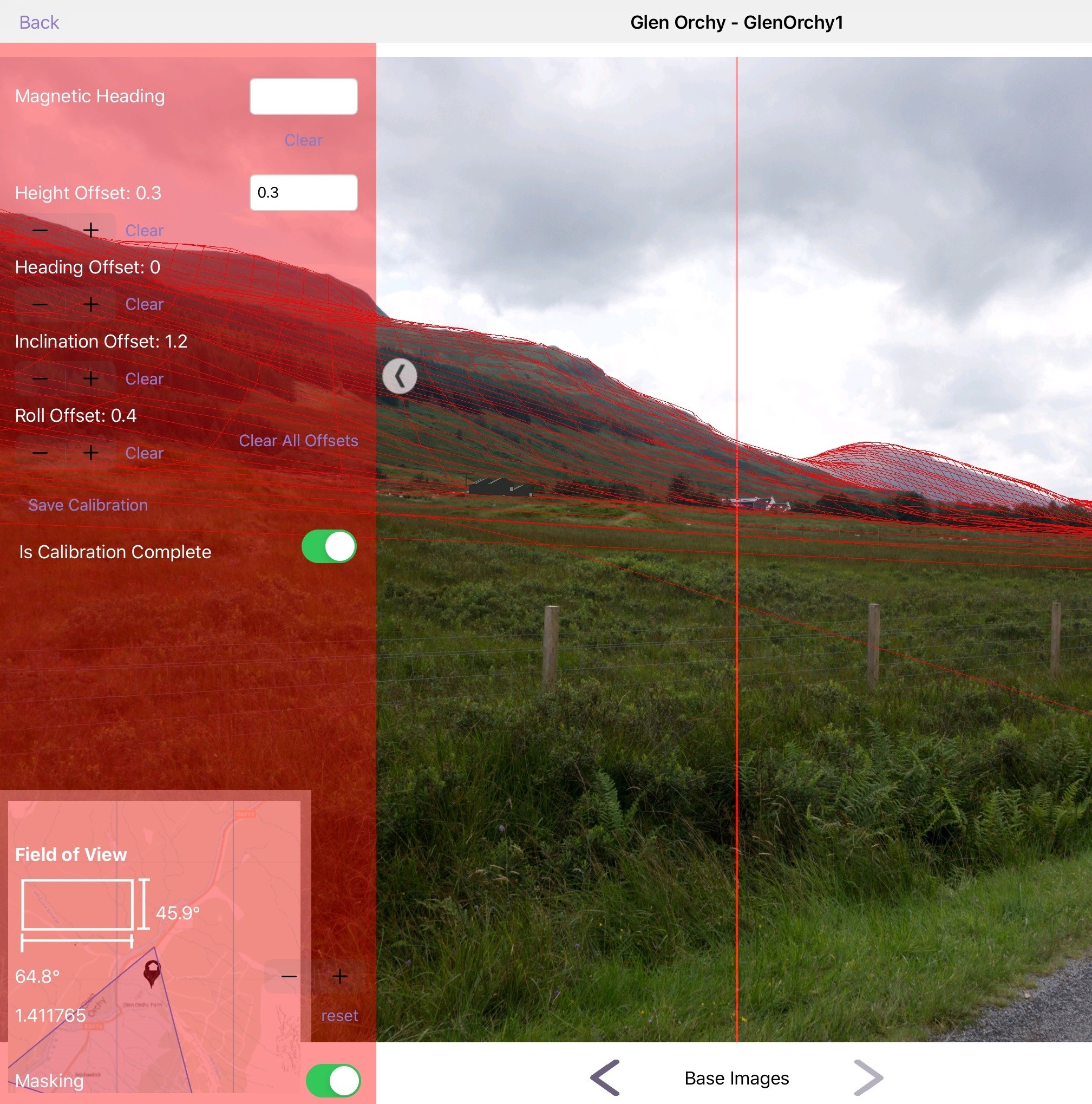
The different functions of the calibration panel are shown below.
| Function | Description |
| Red centre line | A red centre line is shown on top of the visualisation to allow the device to be accurately aligned to the real world |
| Height offset | Raises or lowers the observer height to allow wirelines to be created at altitude (on top of buildings etc.) |
| Heading, inclination & roll offsets | These offsets are added to the sensor input to allow the sensor reading to be calibrated for magnetic variations in a certain location |
| Is Calibration Complete | Saves all calibration settings |
Some functions of the My View calibration panel are not available in the Gallery Calibration panel.
Trace/Foreground masking
To handle situations where the terrain model doesn’t include items found in the field we have included a foreground trace function.
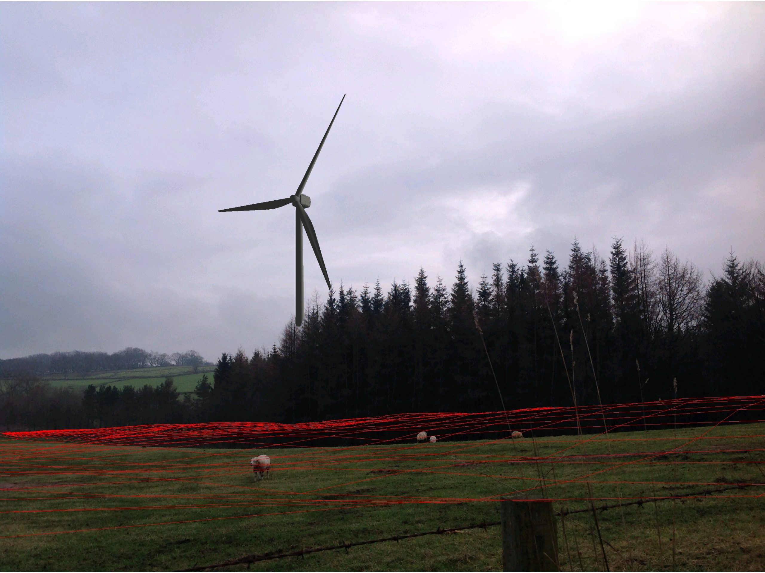
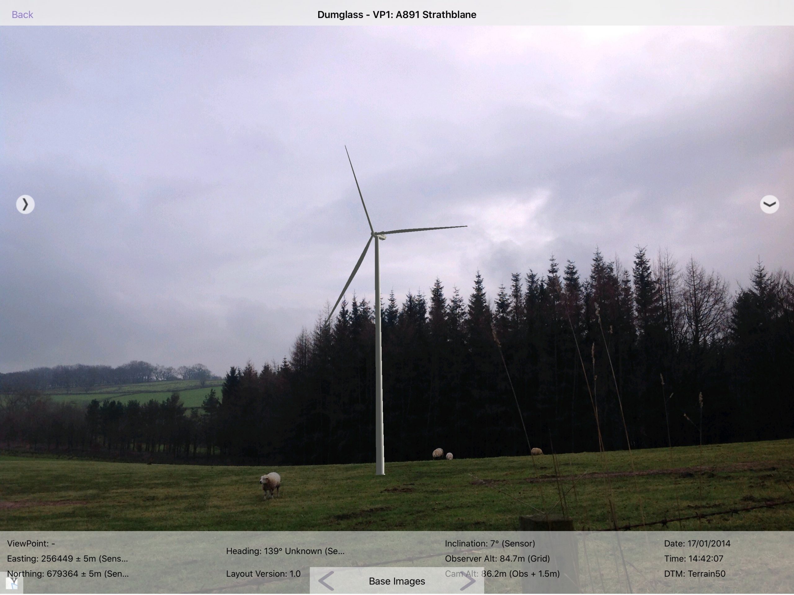
The example below shows the turbine is placed on the far hillside behind the trees. As TVV creates a superimposed wireline, the turbine is in-front of the trees when it should be behind them.
To start a trace, tap Start trace from the right-hand panel. This closes the right-hand panel and allows you to “draw” around the background items that should be in front of the turbine. In this example, an outline of the trees is drawn (by finger). This is shown below with a red highlight to show the path that was traced.
Pro Tip: Use a stylus – A finger has an approx pixel size of 60px, whereas a stylus (such as the Adonit Jot Pro we supply in the Field Kit) has a size of approx 10px making it much more accurate.
From the right-hand panel, you can then choose the trace to show/hide the trace outline and update the gallery image with the turbine appropriately sitting behind the trees.
A trace can be removed by pressing the desired trace and selecting the Remove option.
- Up to 5 traces can be added to a gallery image
- A trace outline cannot be added to a published image.
Creating renders
TVV has a few different types of renders that can be created.
Standard render
A render based on a photograph. Once the Local Capture shown in the gallery has been set up correctly using the tools described above (Gallery Calibration and Trace / Foreground Masking) a render can be taken. A render is a burnt in .jpg of what is shown in the gallery on the screen. It only includes the background image and 3D objects. It does not include the panels (right, bottom, title, map or calibration panels). To take a render choose the Create Render button from the Render tab of the right panel. This adds a render to the available renders for this project.
Wireline render
A render based on the wireline of the terrain. From the gallery image select the “Wireline” shortcut button at the bottom of the Render tab to create a wireline render. A wireline render differs from the standard render: using terrain data to draw a wireline image of the terrain; rather than using the capture as a background image to show the landscape.
Wireline90
A panorama version of the wireline render. Pressing the Wireline90 button from the Render tab of the fly-out panel can trigger this. The wireline panorama as the same as the above, but instead of only rendering the terrain that is visible on the screen, it captures more of the terrain on either side to provide a render with a larger field of view. This works by taking 3 standard renders and stitching then together to make a large high resolution panoramic wireline.
Viewing renders
Renders are shown by changing to the Renders tab of the gallery. Like the base images, all renders displayed are grouped via viewpoints, by selecting a viewpoint on the top left you can view the renders that belong to it. Click on Captures at the top of the gallery screen and tap on Renders.
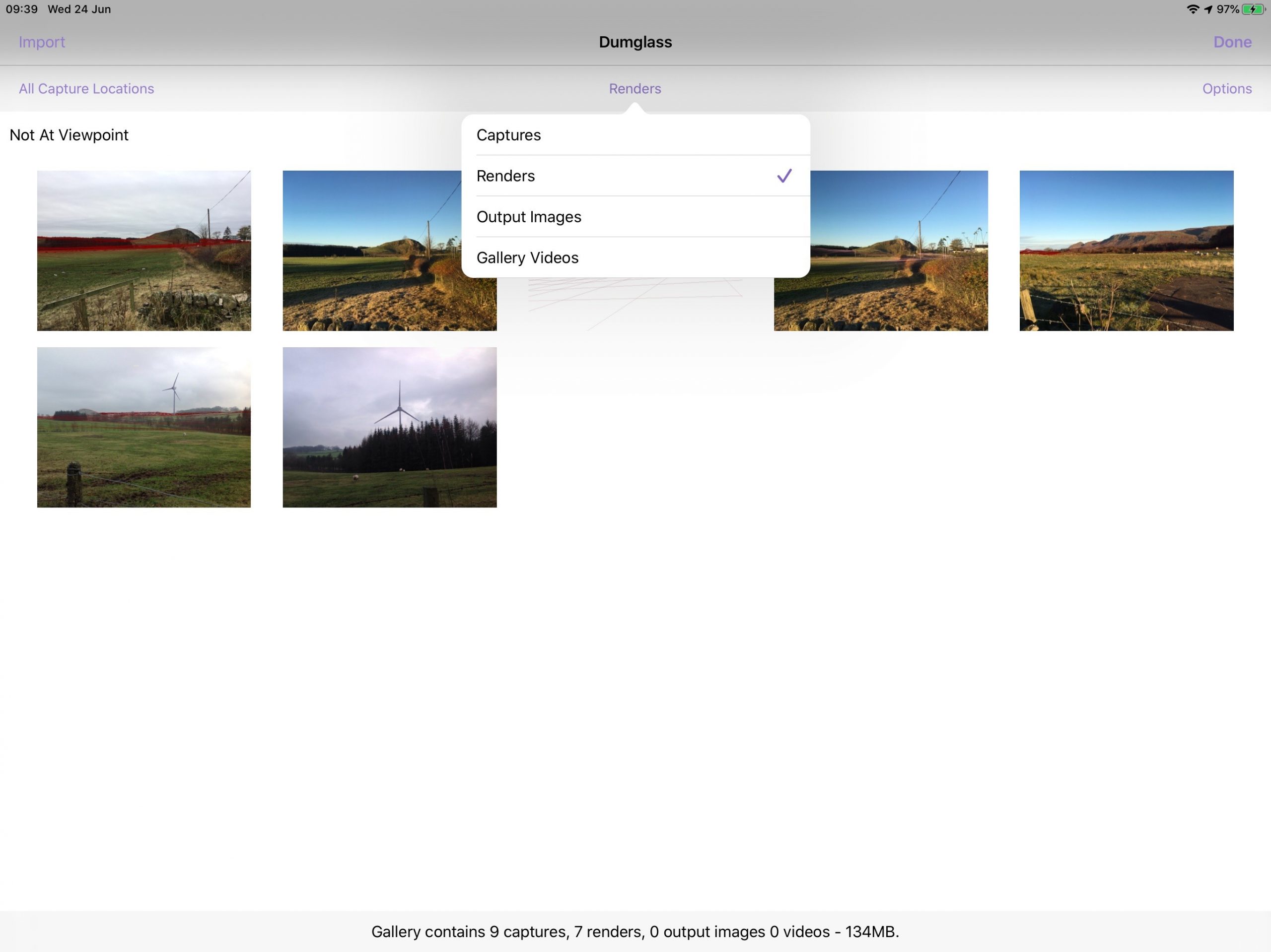
Renders can be selected and deleted (as with Captures). Tap on the Options button then tap on the render you want to delete; then select Delete.
Tapping on a render opens it in full screen mode. From full screen mode, the render can be shared via email or other sharing mechanism built into the iPad.
Renders can be shared back to the portal by choosing Options, then choosing the renders and selecting Sync. These renders will then be available for display in the portal.
Viewing output images
Output images are SNH compliant images that the user can generate on the TVV Portal. There are a number of different types available, all of which can be viewed on the device.
- Baseline Panorama – A 90° x 18.2° panorama photograph (created from 5 DSLR images)
- Baseline Wireline – A 90° x 18.2° panorama render where the terrain is displayed as a wireline (created from 3 wireline renders)
- Photomontage – A 53.5° x 18.2° panorama render (created from 3 renders)
Once a Gallery sync for a project has occurred, any output images that are associated with the project will be downloaded onto the device. From full-screen mode, the image can be shared via email or other sharing mechanisms built into the iPad.
Cleanup gallery
Image galleries can be cleaned up in order to free up space on the device they are using. They can achieve this in two ways.
Cleanup Deleted Media
Cleanup Media from deleted Projects – This can be accessed by tapping the info button in the top right-hand corner of the project list and project details page.

Tapping Cleanup Deleted Media will remove any redundant images, renders and storage in storage that belongs to deleted projects, therefore freeing up space on the tablet.

Cleanup media from project
This removes all images that belong to an active project. Tapping the Cleanup button on the Gallery section of the app will remove all of the images, renders and output images from the project, freeing up space. The user can tap “Sync” to reload the images back to the device.

Distraction-free mode
Enter distraction-free mode by double-tapping anywhere in the gallery visualisation, this will hide all menus and just show the 3D visualisation.
To restore the menus simply double tap again.