
Managing projects
Contents
This section explains the processes required in adding and managing projects within the portal. A project can be wind, solar, grid or building project. The type of project added will depend on the domains added to the TVV license.
Project page
The project page shows the project information entered when creating the project, and a map on the right-hand side which will show the project location once layouts have been created.
The Project page contains five tabs that group information about the project into categories. The tabs shown are dependant on which domain you are using: Wind, Solar, Buildings or Grid.

| Domain | Tab | Description | ||
| All | Details | Add and Edit Viewpoints, Overlays, Reference Structures and Reference PDF | ||
| All | Layouts | Add and Edit Layouts and 3D model locations | ||
| Wind only | Cumulative | View nearby organisational cumulative projects, as well as review a free preview or purchase a full snapshot from the national cumulative dataset | ||
| All | Media | View any media associated with the project (either captures taken from the iPad, base images uploaded from a DSLR camera or renders created as output from TVV) | ||
| All | Published PDF | View any previously published PDF files |
Details tab
Viewpoints
TVV allows Viewpoints to be set using Latitude / Longitude or Easting / Northing. Once set up, from ‘My View’, on the device, the current location can be overridden by choosing the specified viewpoints.
Viewpoints are associated with a Project. They are managed from the Edit Project page.
Adding a single viewpoint
To enter a new viewpoint complete the fields required to add a new Viewpoint (see below) and click Add Viewpoint

| Field | xxx | Description |
| Name | Complete the required viewpoint name. This identifies the viewpoint. | |
| Coordinate System | Choose between WGS and projected to enter coordinates in the appropriate format. If projected is chosen, coordinates will be projected using the projects Projection setting. | |
| Latitude / Longitude | If WGS is selected, the location the location can be entered in WGS Latitude and Longitude. TVV will look up the altitude (from the chosen terrain service) for each viewpoint location entered and store it. | |
| Easting / Northing | If OSGB is selected, the location the location can be entered in OSGB Latitude and Longitude. TVV will look up the altitude (from the chosen terrain service) for each viewpoint location entered and store it. | |
| Is Published | This controls the viewpoint being uploaded to the device. Tick the box if the viewpoint is to be available on the device. Untick the box if the viewpoint is to exist on the website only. |
Click Add Viewpoint
Once added, viewpoints are shown on the map as a green square.
Adding multiple viewpoints
Multiple viewpoints can be added also. To import multiple viewpoints
- Click Import Viewpoints

- Click Choose File to select the chosen CSV file
- Click Import Viewpoints
Click Sample to download the sample CSV file template for viewpoints.
Exporting Viewpoints
To export Viewpoint in CSV format:
- Click the Export Viewpoints
The CSV file exported will have coordinates in the currently selected coordinate system.
If a viewpoint does not contain any Base Images, its location can be changed without removing the viewpoint entirely. To change the location of the viewpoint, click the edit button next to the viewpoint’s location column. Depending on your settings, you will be required to enter the coordinates in either Lat/Lon or Easting/Northing format.
Overlays
All new projects come with a default base mapping overlay. This is based on OS VectorMap District mapping. Clicking on the Preview button will open a popup windows with the overlay data shown as it will be downloaded from within the app.
An overlay is a set of raster files that are grouped together to form an overlay layer to be shown in TVV. All files must be uploaded in one go; additional raster files cannot be uploaded later.

To create a new overlay:
- Select the TIF files and associated .tfw files. These will be added to the Upload Queue.
- Complete the fields required to add a new overlay
- Click Begin Upload to start uploading the queue.
| Field | Description |
| Name | Enter the name of the overlay to be uploaded |
| Overlay Type | This controls the type of overlay – raster or vector |
| Is Default | Determines if the uploaded files will be the default overlay |
Once Begin Overlay is clicked, a progress bar is shown to show the progress of the files to be uploaded. Once the overlay is uploaded, you can get a preview of it using the preview button.
Notes:
- Every TIF file MUST have an associated .tfw file
- Ensure the names of both files are the same – e.g. either all uppercase or all lowercase.
- Maximum single file for upload is 100Mb, please split any larger files into several smaller files.
Recooking overlays
Overlays are cached on our GIS server. If the overlay changes the cache will need to be recreated. This process is called cooking the overlays. The overlay tiles are generated in the background so the portal can be used while cooking is happening in the background.
Reference structures
Reference structures can be made visible on the visualisation screens and are used to help align the wirelines to the terrain using other visible structures.

To add a reference structure to a project:
- Complete the fields required to add a reference structure
- Click Add
| Field | xxx | Description |
| Name | Complete the required reference structure name. This identifies the reference structure in the portal and in the visualisation screens. | |
| Coordinate System | Choose between WGS and OSGB to enter coordinates in the appropriate format. | |
| Latitude / Longitude | If WGS is selected, the location the location can be entered in WGS Latitude and Longitude. TVV will look up the altitude (from the chosen terrain service) for each viewpoint location entered and store it. | |
| Easting / Northing | If OSGB is selected, the location the location can be entered in OSGB Latitude and Longitude. TVV will look up the altitude (from the chosen terrain service) for each viewpoint location entered and store it. | |
| Height | The height the reference structure should be shown at. This will allow the top and bottom of the reference structure to be shown at the correct sizes in the visualisation screens. | |
| Colour | Choose the colour that the reference structure will be shown in. |
Reference files
PDF files are reference files that are included to replacing having to carry so much paper out to the field with you. Any PDF file can be uploaded and will be downloaded to the device as part of the bulk downloader process or on demand.

To add reference files:
- Select the files you want to add using the Select file to Add button. This will add the files to the queue.
- Review the queue to ensure that it includes the files you want to upload
- Choose Begin Upload to start uploading the files to the server
The maximum single file for upload is 100Mb.
Layout tab

A layout version needs to be added to contain all the information about this layout. Once a layout has been created, items to be visualised (turbines, solar panel or transmission towers) can be added to that layout.
A project can have multiple layout versions and they are all created and edit from the Edit Project Page.
Managing layouts
To add a new layout version to a project:
- Click New Layout Version
- Complete the fields required to add a new layout version
| Field | xxx | Description |
| Version Name | Complete the required name or number of the Layout | |
| Is Published | This controls the Version being uploaded to the device. Tick the box if this Version is to be available on the device. Untick the box if this Version is to exist on the website only. | |
| Valid From / Valid To | Control the dates the Version is visible on the device for. Only Versions that are valid on the date viewed will be shown on the device. | |
| Size | Applicable to Wind domain only. Optionally choose the size of the layout: Not Set means this field will not be visible on the device Small 50KW to 5MW (e.g. small-scale community development) Medium over 5MW and up to 20MW (e.g. large-scale community development or small scale commercial) Large over 20MW (e.g. large-scale commercial wind farm development) Very Large over 100MW (e.g. very large-scale commercial wind farm development) | |
| Stage | Optionally choose the stage of the layout: Not Set means this field will not be visible on the device Scoping Operational Construction Planning | |
| Is Public | Makes the project available to members of the public so anyone can download the app to view |
Once Add Layout Version is clicked, the Edit Version page is displayed where you can add turbines, transmission towers or solar panels, or edit other project attributes.
Layout versions can be removed by clicking the Delete Version button on the main project list or on the layout version list on the edit project page.
Please note turbines, solar panels, transmission towers and buildings across layouts must be within 30km of each other.
To assist with the verification and management of Layout versions, the portal now incorporates a simple to use 3D rendering system to allow you to preview your layout online without recourse to your iPad and TVV.
Accessing your Layout as normal, you will now be presented with the standard options to Update Version, View 3D Map and Clone Layout Version.
3D terrain map
Clicking on View 3D Map will take you to a rendered visualisation of the model on the proper landscape you would view using TVV, with either the OSGB texturing or wireline rendering (dependent upon your checkbox selection).
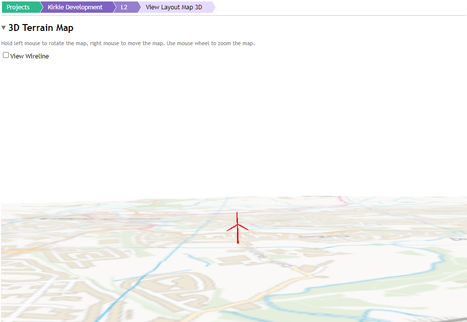
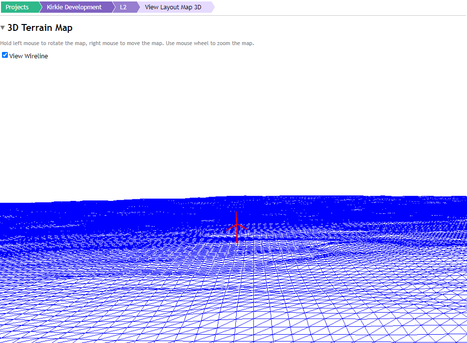
In either mode the following controls apply:
- Hold Left Mouse Button and move mouse: rotate around the point central to view
- Hold Right Mouse Button and move mouse: strafe around the terrain moving in straight vectors.
- Hold Middle Mouse Button and drag the mouse towards/away: zoom the terrain view in and out
- Scroll wheel: Zoom the terrain view in and out.
Adding 3D models
Adding a 3D model to the project will depend on the project type. The type of project added will depend on the domains added to the TVV license.
Adding a single model
Models are added to a layout version through the Edit Version page.
To add a new turbine: Complete the fields required to add a new model – see below:
Turbines:




Click Add Turbine/Transmission Tower/Building/Solar Panel
| Field | xxx | Description |
| Reference | Complete the required number to identify the model | |
| Type | Choose the required model type from the drop-down list. Model Types are described in [Adding an Item Type]. | |
| Coordinate System | Choose between WGS and Projected to enter coordinates in the appropriate format. If projected is chosen, coordinates will be projected using the projects Projection setting. Coordinate systems are described in [Displaying Coordinates]. | |
| Latitude / Longitude | If WGS is selected, the location can be entered in WGS Latitude and Longitude. TVV will look up the altitude (from the chosen terrain service) for each medel location entered and store that too. | |
| Easting / Northing | If OSGB is selected, the location can be entered in projected Easting and Northing. TVV will look up the altitude (From the chosen terrain service) for each model location entered and store that too. | |
| Rotation | Choose a rotation amount in degrees (applicable only for Transmission Towers) |
Once added, the turbine, solar panel, transmission tower or building will be shown on the map.
The Reference and the Model Type can be edited, but you cannot edit the location, therefore if you wish to change the location, you will need to delete the model and create a new one.
- A Reference can be edited by selecting the reference and typing the new reference. The reference will only be saved when return is pressed.
- The transmission tower rotation can be edited by clicking on the ‘Edit’ button, updating the rotation and clicking ‘Save’
Transmission tower order can be edited using the up and down buttons.

Adding multiple models
Multiple models can be added also. To import multiple models
- Click Import Turbines/Transmission Towers/Buildings/Solar Panels
- Click Choose File to select the chosen CSV file
- Click Import Viewpoints
Click Sample to download the sample CSV file template for viewpoints. The Sample CSV file changes depending on the coordinate system to be used.
Exporting models
To export items in CSV format:
- Click the Turbines/Transmission Towers/Building/Solar Panel Banks which can be found in the Layouts tab of a project by clicking on the edit button associated with the layout you wish to export from
- The CSV file exported will have coordinates in the currently selected coordinate system (Please remember this will export all the items from the layout as a CSV and does not export only the ticked)
Configuring Tower Grid Connection Points
To make the app draw conductor lines between grid towers when using visualisation, you will be required to configure the conductor connection points on the portal. These are the coordinates where the wires connect to the portal.
- Click Settings
- Edit a Tower Specification
- Conductor Connection Points will be a new section below the Grid Tower edit form.
Users will then be able to add coordinates using either the form or the CSV importer.